The light density factor (gain-factor)
Those who buy a screen for the private or for the professional use will repeatedely come across to the light density factor in the data sheets and prospects that is also called the gain factor. This important parametre is mentioned as a kind of feature in many screens as the clock speed of the processor of a computer or the size of a hard disc in gigabytes.
But there is much more behind the gain-factor than a feature; it marks the light radiation properties of a screen into a determined direction. Due to this reason, it actually makes no sense to indicate the gain factor for a screen as a mere number. In the following chapters we will explain what is exactly behind it and what can be done with a mere number in the data sheet of a screens.
Introduction and motivation
Before we dare to get into the physical-mathematical definition of the light density factor, we will first try to understand the problem by means of some phenomenons of the daily life we all now. Those who can still remember the time of the flat screens will know that in the case of the first models, those users who sat right in front of the screen could enjoy a fantastic and flickerfree image. But as soon as this user wanted to show something to his friends or colleagues and a small group took a seat around him, a big to-and-fro and up and down moving started, as the image could be only perfectly recognized from the front. Today, this problem is mainly solved, even though some low-cost TFT-screens also do not provide a perfect image in case of a strong sidelong glance.
Let us imagine this phenomenon in a cinema: The fortunate visitors sitting on the middle seats enjoy a perfect image, while the "marginal figures" realize a strongly weakened image. This is unacceptable! In a cinema, the screen must be of a quality that the incidenting light is uniformly reflected in a good angular range, so that everyone of the audience gets his money worth.
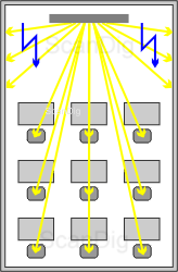
But there is also a contrary situation: In the beginning phase when the beamers and projectors still were very faint, no light should be wasted. In a narrow room where the audience sits, it does not make sense to reflect a major part of the radiated light to the side walls; finally, the image must reach the audience and not the wall. In order to avoid a total darkening of the room by applying a faint projector, the screen should somehow bundle the light in direction to the audience and not in all directions.
The adjoining image should clarify this problem: In an elongated training room where 9 participants are gazing spellbound at the screen image of the lecturer, the viewing angle of the audience is in an angle range between n 0° and 30°. The light that is released by the screen to the walls of the room is wasted and unwanted, this means that a major part of the light that is radiated by the projector does not reach the audience. If the beamer in use has a strong luminosity, this loss of distribution does not play any role and can be projected even during the day light. If, in contrast, in case of a faint beamer more than half of the light is wasted and projected to the walls, there is too less light reaching the audience so that the room has to be darken artificially. As the beamer or the projector cannot determine how the light radiated by it is reflected, it is the task of the screen to bundle and reflect the incidenting light in a way that it reaches the audience in a uniform way and not the walls.
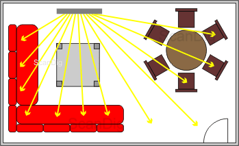
Now, as a second example, we have a look at a typical german living room with a sofa corner and a dining area. Here, we have completely different conditions than in our training room: there is the executive position on the sofa, thus the person who looks straight to the screen. But the rest of the family sitting on the sofa also wants to fully enjoy the film. Eventually, a part of the family is sitting at the dining table and only wants to watch some of the tense scenes just "by the way". Thus, in such a living room, the audience sits in an angle range of approximately 0° - 80° spread in both directions. All want to get some of the light radiated from the screen. Thus, in contrast to our training room, the light is supposed to be reflected almost uniformly to all directions; eventually, the executive chair right in front of the screen is more oftenly used than the other seats, so that it is supposed that it is specially well reflected to this place. A similar situation prevails also in a cinema where the viewing angle of the top-seats are from 0° horizontally and vertically up to some high angle degrees for the seats at the edge of the first line.
Thus, at the end of this subchapter, let us hang on to the fact that there are different situations in which the screen in use should accomplish a determined effect concerning the reflection of the incidenting light. I want to anticipate that it is due to exactly this effect that there are different screen types. And in order not to describe this effect with some general words but also with figures, we introduce now the so-called light density factor.
Definition of the gain factor
In the previous chapter we have realized by means of some practical examples that there must be different screens with different reflection properties in order to cope with the respective projection situation. Expressed in a more technical way, this means that
 a certain screen is supposed to reflect the light that incidents on it with a certain intensity to the one and with another certain intensity to the other direction. In order to describe the intensity of the reflection in figures, we use the light density factor β. Let us risk to jump into the cold water and read the definition of the gain-factor, as written in the German Industry Standard Norm DIN 19045-4 ("Projection of moving and still images, part 4: Reflection- and transmission properties of screens"):
Definition: The light density factor βP is, according to DIN 5036, the relation of the light density LP of a screen sample for a determined view direction to the light density LW of the totally diffusing and totally reflecting surface (white standard) for a determined direction of radiation.
Everything clear? Or did you not understand one word said? Such a definition is, of course, a little doozie, also because it indicates a further standard DIN 5036. Let us try to shed some light into this. First, the term light density appears two times. I exactly explained on our Photometry-page what the light density is: it is a measure for the brightness of a light source and/or a light reflecting surface. The more intensive the surface radiates, the larger is its light density; moreover, the light density is the larger the smaller the radiating surface is. If we simply keep in mind that the light density indicates how bright a certain surface radiates to a certain direction, we can understand the definition of the gain-factor:
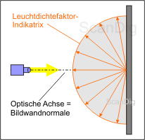
We take a small piece of our projection wall, a so-called projection screen - sample, and radiate it. Then we measure the light density by means of the so-called photometre in a determined direction, for example, vertically to this surface. Thus, our photometre provides a certain numerical value for the light density LP of our projection screen - sample. Then, we exchange our small piece of screen with another piece of screen, whereby this surface is supposed to reflect absolutely in all directions and with our photometre, we measure again the light density LW. Now we have two measurements from which we can calculate the quotient and obtain therewith the light density factor. The remaining question is what is a totally diffusing and reflecting surface.
Therefore, we will have a look to the illustration above, on which a projection screen is vertically radiated by a light source; this means that the optical axis of the light is equal to the reflection screen perpendicular. Thus, the ray falls vertically on the screen and is reflected by it. The term "totally reflecting" of the above definition means that all the incidenting light is reflected, thus not the least amount is absorbed (swallowed) or transmitted (let through).
But in the definition, the term "totally diffusing" is more important: This means that the incidenting light is totally diffused to all directions. This is represented in the image by a semicircle that is reality is, of course, a hemisphere. Thus, the incidenting light is also diffused to all directions uniformly and without any deductions, so that they get the same amount of light from any angle of the projection screen. A surface with such features is called white standard, a thing that is only approximately achieved in practice. The technical term for the semicircle that illustrates the intensity of reflection of the light is Light density factor-indicatrix. Now we can also assume that a projection screen with such uniform features has a gain-factor of 1,0 in all directions.
The light density factor-indicatrix illustrates the radiation behaviour of a screen. For a totally diffusing and totally reflecting surface (white standard) is a semicircle that symbolizes the light density factor in all directions.
Now, one of course wonders how such an indicatrix for a real screen looks like? The following image shows an example for a screen type D. The black semicircle shows the indicatrix for our totally diffusing and reflecting surface of the previous image as a reference. The respective gain-factor is &betaW = 1. The red semi-ellipse shows the actual light density factor-indicatrix for this projection screen. Again, I would like to mention that it is actually not an ellipse but an ellipsoid; it is obtained by rotating the illustrated ellipse with the red frame by the optical axis.
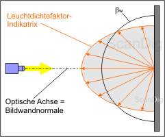
By comparing the red ellipse with the black semicircle, we can read that this screen reflects more intensively in direction to the screen perpendicular as to the direction of the edge. The gain-factor is located in direction to the perpendicular, thus approximately at 1,2. To the contrary, for the gain-factor that is vertically located to the perpendicular, we can read a value of approximately only 0,8. And at an angle of approximately 60° to the optical axis, the red ellipse interfaces with the black semicircle; here, the gain-factor is exact 1,0. Thus, the behaviour of such a projection screen could be described as follows: Those who sit right in front of it will get a lot of light; those who sit diagonally to it will percept some normal lighting conditions; those who sit laterally to the screen will still recognize the image. The best seat in the room depends, of course, from the brightness of the projector and the brightness of the room.
Specially by looking to the second image everybody should know what a light density factor is. And - this is very important - it also gets clear that the radiation behaviour of a projection screen cannot be described with just one factor, as such a gain-factor can be only applied for a very certain direction. Thus, in order to describe reflection behaviour of a screen completely, the producer should indicate the gain-factor for the different viewing angles or simply add an image of the light density-indicatrix. This point is also of such an importance to me that I repeat it again:
The gain-factor indicates the reflecting behaviour of a projection screen in a certain direction. In order to describe the complete radiation behaviour of a screen, there is either a table needed which indicates the gain-factors to certain angles or a graphic illustration as a light density factor - indicatrix.
According to that fact, what sense does it make if a producer describes a certain screen with a gain-factor of 1,2? According to the above mentioned, it is certainly right that this value is only applicable to one direction that is for the screen perpendicular, but from this value in direction to the perpendicular, the approximate reflecting behaviour to the other directions can be derived according to the illustration above.
Measure of the light density factor
Now that we know what the gain factor is and from which two values (light densities) it is calculated, the question how the gain-factor of a screen is measured arises. According to the definition of the gain-factor, this sounds very simpple: We buy a device to measure the light density, radiate a piece of screen, measure the light density, replace then the piece of screen by a standard screen, measure again and calculate the quotient.
But the matter is not completely as simple. First, we do need an aproppriate light source, and therefore, any kind of lamp is not adequate but this lamp must produce a standard light according to the DIN 5033-7 standard. Such a light source can be acquired in a specialized shop, as it is also the case of a device for measuring the light density. But the actual problem is to get a totally diffusing and reflecting surface of reference, as such a thing does actually not exist at all. Instead, a so-called Reflecting standard is used. This is - simply expressed - a small piece of projection screen that certainly is neither totally diffusing nor totally reflecting, but which
 features are known. In other words, with such a reflecting standard, the respective indicatrix is included as a table or a graph; thus, for every viewing angle we know the respective light density factor βN, that forms the quotient resulting the light density of the reflecting stantard and the light density of the white reference. Now, we accomplish the measurement of the light density once with the projection screen-sample (our real screen) LP and once with the working reflecting standard LN , and we get, according to the above stated formula, our gain-factor &betaP. Also here, it should be emphasized that we have to measure and to calculate the light density factor for each of the viewing angles; thus we always get a βP(ε), whereby ε is the viewing angle that is relative to the screen perpendicular. Let us resume the core messages of this chapter in the following frame:
In order to measure the light density factor βP(ε), a standardized light source, a device for measuring the light density and a working reflecting standard with the known reflection properties βN(ε) are needed. The measurement has to be accomplished for each one of the viewing directions ε.
Finally, there is to mention that this procedure of measurement that I did describe in a very simplified way actually is quite laborious and complicated. Not least, there is no working reflecting standard that constantly keeps its light technical features; thus, in addition, also the working reflecting standard have to be repeatedely calibrated with the right reflecting standard.
Illustration of the gain factor by means of distribution curves
We have learned in the previous chapter that the light density factor βP(ε) can be always only measured for a very certain viewing angle β. Thus, in order to get a founded statement about the radiation behaviour of a screen, several single measurements are needed with different viewing angles.
| Viewing angle |
Light density factor |
| 0° |
1,4 |
| ± 20° |
1,2 |
| ± 40° |
1,05 |
| ± 60° |
0,8 |
By compelling such a series of measurement in a table in which for the different viewing angles the respective light density factor is mentioned, one can easily get an overview of the reflecting behaviour of the screen. Those values that do not appear on the table can be calculated by means of the interpolation. But in order to quickly get an overview about the radiation behaviour of the screen and specially also to compare different screens with each other, such a gain-factor-table is less adequate. In this case, a graphic illustration of the reflecting behaviour is more recommendable.
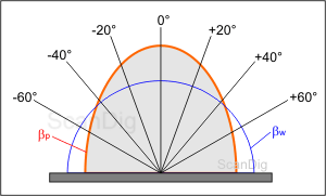
For the gain-factor, there are two common ways of illustration: the appliance of cartesian coorninates or the appliance of polar coordinates. Let us start with the illustration in the form of polar coordinates, as we already got introduced to them in the penultimate chapter. The adjoining image visualizes literally the reflection behaviour of a screen. Starting from the screen perpendicular (0°-line), some lines are arranged in some regular angles (here: 20°). These lines are each representing a very determined viewing direction. The blue white-reference curve serves as reference curve with a constant gain-factor of 1. We apply the measured values of the light density factor on the respective angle-lines and communicate these points to the red curve that finally visualizes the reflecting behaviour of the projection screen for the incidenting light angle of 0°.
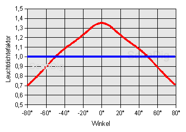
An alternative way of representing the distribution curve of the light density factor takes place in the cartesian coordinates. The adjoining image shows exactly the same contence as the polar coordination image above. As it is the case in a very normal illustration, we apply here each of the viewing angles on the x-axis and the respective measured light density factor on the y-axis. Our blue white reference curve with the constant gain-factor of 1 becomes a straight on the illustration and our distribution curve for the measured screen becomes a symmetrical mountain hill. The advantages of this way of illustration are that we can read the numerical values right from the illustration and that we clearly recognize the light in the maximum range.
The preferred way of illustration depends on what is supposed to do with it. Those who want a rough overview of the reflecting behaviour of a screen are better served with the visual illustration in polar coordinates; but those who need the concrete numerical values for the layout of a professional presentation room will need the cartesian illustration.
Finally, I would like to emphasize that either the tabular form consisting on viewing angles and the respective gain-factor, as also the visualization in polar coordinates or cartesian coordinates have the same physical contence.
Back to the index projection screens
|