Colour management - Introduction and basics
on this page there is a detailed, easily understandable introduction into the topic of color management. The term colour management is a mystery for many users or an unimportant term or a topic which may be reserved for professional users. However, colour management concerns any PC user. Everybody who had to do with digital image files is involved with colour management directly or indirectly.
Colour management is not a matter to leave to professional users. Everybody, who makes digital photos, digitizes analog film material, watches and edits digital photos at the PC, makes prints or copies, should learn at least the basics of colour management.
Problems with digital images in everyday life
First I want to show with a couple of examples how everybody, who has to do with digital images, is concerned by color management, without searching for the reasons and solving the mentioned problems.
- Althouth you are a proued owner of a very expensive digital camera, you get images, where one color (e.g. blue) dominates; a typical case of a wrong white balance in the digital camera or of an uncalibrated computer screen.
- Digital photos appear much more true color at the PC in the office or at a friend than at one's own screen. A typical case of differently set screens without standardized calibration.
- Digital photos have to be edited after purchasing a new PC display, although they have been edited already in detail. Many users do not correct the real image within the image editing process but the errors of a computer screen, since this is not calibrated. When purchasing a new monitor a new image editing of all pictures is neccessary.
- Some digital pictures have true and real colours on the own computer screen; when printing them on photogrpahic paper the colours are washy, pale and have colour fogs. Often the reason is in a bad paper or ink quality, however the reason also may be that the printer just is not profiled.
- The colours of photo prtins made in a photographic laboratory from digital images are not equal to the colours of the original image file. One quickly thinks that an error has occured in the photographic laboratory, whicht might not has implemented a colour management process and uses uncalibrated machines and printers. However, the reason also might be, that the photographic laboratory uses professional devices and produces true colour prints, whilst oneself works with an uncalibrated monitor and has seen bastardized images up to now.
- An image file has different colours on one's PC if you open in with a simple viewer instead of Photoshop®. The reason is that Photoshop® supports colour management and considers colour profiles at the display of colours, whilst a simple image viewer ignores a colour profile which is embedded in the image files.
- You have digitized hundreds or thousands of slides or negatives with a film scanner in hard work, and then you have to postprocess each image in a time-consuming image editing process, since the colours of the scans do not correspond to the original colours. The reason is either an uncalibrated scanner or an uncalibrated computer screen.
Many users can sing a song about the problemes mentioned above. And often one searches the fault in the digital camera, in the scanner or in the printer. However, the real fault is in most cases that the colour mangement is not complete, i.e. one works in an environment, where the chain scanner - screen - printer or digital camera - screen - photo laboratory is not calibrated/profiled.
In the following chapter we look at an example where the missing colour management has an effect on each element in such a chain, where colour errors propagate and become worse and worse.
Example for the propagation of colour errors
Assume we have an analog 35mm slide with a red motive (e.g. a red picture, a red dress or simply a red card), which we digitize with a scanner, then we view it at the computer screen, edit it in the image editing software and finally print it out with our printer. Our red motive may have an intensity of 100 (whatever this might significate) and shall be printed on phtographic paper.
Figure 1 shows the original situation on the left side: a red card with a the red tone of 100. No we digitize our analog picture with the help of a scanner. Our But our scanner has the negative property that red shades are scanned 20% darker. From our original motive we will get a digital image file with a red tone of intensity 80. Fiture 1 demonstrates this situation in the second stadium with a darker red. A scanner with a colour deviation of 20% surely is not a premium device; however, many scanners in the lower price range produce much too dark scans and have considerable colour errors.
Now we look at our scanned image at a computer screen. This screen may be set in a way that red tones are displayed 25% darker thank original. Fomr our red card with a colour intensity of 80 now we get a dark red card with a colour value of 60. Attention! The digital image file still contains the information that it is a red tone with value 80, only the computer screen displays the red tone 80 as a red tone 60. Is something like that in daily life possible at all or at least probable? Of course! If you just come from watching a movie from a DVD with your PC you might have reduced brightness and contrast on your screen. Or if you have written a letter last evening just using your screen and a small desk lamp as light source, you may have reduced brightness and contrast of the screen in order not to blind your eyes with a white text document.
So we are at point 3 in the above figure and open the digital photo with an image editing program. In that it appears much too dark and we correct the image brightness with the brightness controller in such a way, that the image on the screen corresonds approximately to the original image; apparently we correct from 60 to 105, for example, which corresponds to a brightening of about 75%. But what do we really correct? Our image file still has stored the colour value 80; if we increase this by 75% we get the value 140 (4. part in figure 1). Now we are approximately 40 points over our original image. The image appears on our faulty screen with good colours, however, the image file contains a much too bright value for the red tone. If that does not take a revenge later...
So what have we done in the image editing program? We have corrected the error of the scanner, whisch produced too dark scans. And we also have corrected the much too dark screen. On our wrongly set screen this image file now appears in its original colors, even if its red tone has value of 140. On a different screen this image file will be displayed much too bright.
Let us come to our last step, namely the output of the image file on a printer. Assume our printer prints colours much too bright (e.g. 30% brighter), then our red tone with value 140 will become a red tone with value 182, see part 5 in the above figure. This read tone as less similarities with the original red, the image seems completely alienated, everything else than original. We are very disappointed from the result. Let us summarize:
In a production process with different input and output devices at each station there occur colour errors which can propagate or even intensify.
Is this example not unrealistic or exaggerated? Of course we have used extreme errors, which do not occur in that intensity if high-value devies are used. However, if you own a scanner/printer in the double-digit Euro-area and have an old screen, used for different applications, you have to calculate with such heavy deviations of the singular devices.
How fatal such colour errors really are depends on the specific application case: If a football referee prints the originally red card on a cardboard and shows a this bright red card to a football player, there is no discussion, the player has to leave the court. There is no compromise like "May I continue to play for e.g. 10 minutes, since the card is only light red". However, if the red motiv is a ladies blouse for a fashion catalog, then the mail order company has to expect many returns since the customers will recognize completely different colors in reality than on the catalog picture, and the blouse may not fit to the desired skirt etc.
Motivation for a colour management process
Our example from the last chapter has shown that in a process chain (scanner - screen - printer) errors occur in every station, which akkumulate in the worst case or annull in the best case. It would be a piece of luck if the scanner scans 20% too dark and the screen displays colours 20% to light. At the latest at the printer or after purchasing a new monitor the result will be disappointing. So what can be done in order to leave colour errors not to the coincidence?
If you have millions on your account you invest 100.000 € into a drum scanner, buy a special graphical screen for 10.000 € and invest another 10.000 € into a professional photo printer. Then the errors of the singular components are so small, that you get only tiny colour deviations. But even minimum colour errors are still inacceptable in the professional field, i.e. when printing high gloss magazines. Thus one needs a clear, reliable solution, which also works in the low-cost area.
In our example we have used a scanner which digitizes medium red tones 20% too dark, a pretty bad device. Anyway, this cheap scanner wouldn't be so bad if we knew exactly that those medium red tones are digitized 20% too dark. Compare: A watch which is too slow by only 5 minutes may be the reason that you miss many trains and appointments and thus is quite unusable; however, if I know exactly, that the watch is too slow by 5 minutes, I can get along with it quite well.
So if we succeeded in measuring the colour errors of a scanner exactly and write down them in a kind of correction table (e.g. from red 100 make red 80, from green 70 make green 65, from blue 150 make 167), then our scanner would still deliver image files with colour errors, however, we could correct them using our correction table. And this is exactly what happens at the scanner calibration in a colour management process:
In a colour managemtent process a scanner is measured with a reference original and is calibrated. The result is a scanner profile which can be sued for the correction of the image files.
A professional scan software like SilverFast first measures the used scanner, stores the error information in a profile file and then corrects automatically each image, which is digitized with that scanner. The user does not really see this correction process and ist just happy to automatically get corrected image files with true colours which correspond to the original.
What I have described here in detail for the scanner also holds for the screen, the printer or a printing press. If the errors of the singular devices are known they can be stored centrally and used for the colour correction. If you have found out by a measuring that your screen makes red 80 from red 100, blue 89 from blue 75 and yellow 134 from yellow 125 these error information can be stored in a screen profile and used as a correction measurement, when an image is displayed at the screen. Of course this evokes a small time shift since the image cannot be displayed immediately at the screen but has to be converted first.
And of course also the used printer should be measured exactly and the measured errors should be stored in a printer profile centrally, so that they can be used when printing an image file. From these deliberations it becomes clear that we can live with our errnous devices (scanner, screen, printer, proof system) quite fairly, if we measure the singular devices, store the colour errors in a device profile und use it for the correction.
Figre 2 illustrates our desired state: If we know the colour errors of the scanner, the screen and the printer (in the example scanner -20%, screen -25%, printer +30%) we can use the error information in the image processing chain for the correction. In order to measure the errors of singular devices and compare them with each other it is neccessary that all devices have a commeon colour reference, according to this errors are measured and stored. In figure 2 the scanner still scans 20% too dark and delivers a red tone of 80 instead of 100. The correction value of 20, however, can stored in the image file. Also the monitor still shows the red tone 250% too dark; a corresponding colour correction of 20 can be considered when displaying the red tone, so that that the original colour of 100 will be displayed. In the image editing program there is nothing to do, since the displayed red value of 100 is equal to the original colour value of 100. The printer would make a taonal value of 130 out of the value 100. However, since the colour error of 30% is well-known, this can be applied for the correction, so that the real color value of 100 will be printed.
It remains the question what exactly means red 140 or blue 175. If you think such values are something like RGB values, and a colour like RGB(140, 0, 0) is unique, you are wrong. Clear is only the matter, that on a red skale from 0 to 255 the value of 140 is somewhere in the middle. How bright this value is displayed on a screen or printed on a printer depends on the device itself. The measuring and profiling of our devices does not effect a lot, if we do not have a unique reference for the colours, so that the colour value of 140 is interpreted equally on each device. So we need a kind of colour reference, where it is described exactly, how bright or dark a donal value of 140 must be, independent of the device, no matter if scanner, screen or printer.
The profiling of some devices is only constructive if all devices have a common reference colour space.
Up to now we have derived two essential basics for a colour management process: There must be a common reference colour space, which is independent of devices and holds for all input and output devices. In this colour space it must be described clearly how a colour with a specific value has to be, no matter if on a screen or on paper. All devices (digital camera, scanner, screen, printer, proof system, printing press, printing machine) have to be measured and profiled. The profiles have to be used as correction profiles directly at the input and at the output. Thus, for a colour management process we need:
- Definition of a device independent reference colour space
- Definition of generally valid profile files
- Methods for calibrating input and output devices and for creating profile files
- Tools for converting colour spaces and profiles
Reference colour space CIE-Lab
In the previous chapter we have derived that we have to profile alle devices which are a part of the image treatment and that we need colour references which are generally valid and do not refer to one specific device. On our page about colour models we have got to know the additive RGB colour model and the subtractive CMYK colour model. These well-known colour models are technical, device dependet colour models. What does that mean in practice?
In the device dependent RGB colour space a colour is compsed by three values for red, green and blue. A computer screen, for example, makes the colour yellow from the RGB value (200,200,0) by makeing the yellow and green LED of a pixel very bright and switching off the blue LED. Furthermore it generates a pretty dark grey from with the RGB value (100,100,100) by setting the red, green and blue LED of a pixel quite week. At the used terminology "quite week", "pretty dark", "dark", "very bright" you can see, that the resulting colours are not described clearly but consciously ambiguous. They are just device dependent colours, and if on my monitor "pretty dark" is sufficiently bright, it might by quite dark on a different monitor, or even black.
Similarily colours are made when printing according to the subtractive CMYK colour mode. Each printer and each printing press know exactly how to deal with a CMYk-value of (255,100,50,0), however, what finally comes out on the paper varies from model to model, since the colours are device dependent. So how can we describe colours absolutely, what can we take as a reference?
The international commision for illuminance (CIE - Commission Internationale de l'Eclairage) works on the standardization of colours and colour models, which are not oriented at specific devices but at the human perception. In time consuming experiments standard spectral curves were developed for different standard observers, and the human colour vision was described in mathematical models. A a result, which is still a valid standard, the CIE presented in the year 1976 the L*a*b*-colour model.
In the device independent colour model Lab the L stands for Luminance and has a value range of 0 (black) until 100 (white). The values a and be stand for the colour components in a two dimensional coordinate system, where a is on the x-axis from green to red and b is on the y-axis from blue to yellow. All in all you can image the Lab colour model as a sphere, where the L-axis connects both poles from white to black.
With the Lab colour model it is possible to define colours uniquely and noninterchangeable. And even more: With this colour model it is possbible to describe colours mathematically exactly, to calcluate colour differences easily, to define limits for perceptible colour differences and to calculate with colours and colour differences.
With the Lab colour model colours, which are oriented at the human perception capability and not at specific devices, can be treated with the computer.
So the CIA Lab colour model is a standardized, device independent colour model, which servces as a reference for a colour management process. Detailed derivations of the colour modell and visualizations and mathematical backgrounds would exceed the content of this page. There is good literature available about this topic, e.g. from Rolf Gierling or Andreas Kunert.
If you concern yourself with colour management you don't need to know the detaile of the CIE Lab colour space. Important is only, that you remember, that common colour models like the additive RGB model and the subtractive CMYK colour model depend on specific devices and are used for a technical description of colours, whil the Lab colour model is device independent and is oriented at the human sense ogan eye. The Lab colour model is used as a reference colour space in colour management.
ICC profiles
In the previous chapter we have found a device independent colour space with the CIE Lab model, which we can use as a reference for profiling input devices (scanner, digital camer) and output devices (printer, monitor). The question is now, in which form we store such a profile for a device? You can imagin that in open systems (computer, printer, scanner of different manufacturers, different operating systems etc.) a general valid standard for such profil files is inevitable.
Such a standard are ICC profiles, which are available since 1993 an have a version (e.g. 4.0.0) like PC software. ICC stands for International Color Consortium, which numerous large PC manufacturing companies, hardware and software manufacturers belong to. ICC colour profiles are internationally standardized and are independent from computer platforms and operating systems.
The adjacent figure 4 shows schematically the structure of an ICC profile. Each ICC profile has a header, in which basic information about the actual profile are stored, e.g. the size of the profile, the profile type, the preferred colour management modul, the creater of the profile etc. The header of an ICC profile can be read by a colour management software and the information can be made visible. The tag bable contains a list of all tags, which are contained in the third part of the profile. This Tag-table also serves for a quick overview of the profile content for the colour management software.
Principally there are three different types of profiles: Input profiles (internal designition scnr for scanner) are used for scanners and digital cameras. Monitor profiles (internal designition mntr for monitor) are used for screens of any kind. Output profiles (internal designition prtr für printer) are used for output devices of any kind, i.e. printers and printing presses. Additionally there are a couple of special kinds of profiles, with which the normal user is not confronted to.
The structure of an ICC profile is internationally standardized, however with the above figure you quickly realize, that there is an enormous flexibility within the profile. ICC profiles can be very small (e.g. only a couple of hundred bytes) but also huge (several megabyte). There are two main kinds of ICC profiles: Matrix profiles and LUT profiles. Matrix profiles are set up very simply and are used for monitor profiles, for example. In such simple profiles easy relations or characteristic points of a profile curve are stored.
Matrix profiles are not suitable for an exact profiling of output devices. Instead, LUT profiles are used. LUT stands for Look-Up-Table. You can imagine lookup-tables as described in the second to last chapter: A colour value of (100,50,0) is related to the real colour value (110,55,0), a second colour value (100,60,0) is related to the value (110,65,0) and so on. Such a look-up table may contain hundreds or thousands of relations. The more such values are stored the more exact is the profile. LUT based ICC profiles indeed can have the size of several megabytes. The more colour fields are measured in a printer profiling process the larger the look-up table becomes, but the more worthful is the created profile.
Now what happens with such an ICC profile if an image file is to be printed out, for example? If a colour management software finds the colour value of (110,50,0) for a pixel of the image file it looks in the LUT for the printer and finds the corresponding value (110,55,0). Then it sends this corrected value to the printer. of course in a Lookup-table not for any colour value a correction value can be stored; the colour management can interpolate the desired value between available values. Example: The CMM software finds the colour value (100,55,0) in the image file. Then it interpolates from the stored value pairs (100,50,0) → (110,55,0) and (100,60,0) → (110,65,0) a medium value of (110,60,0). Let us summaize at the end of this chapter:
ICC profiles are internationally standardized and have a standard structure. There are matrix absed profiles for simple colour space like at monitors and there are complex profiles with look up tables for the exact profiling of printers.
In the following chapters we have a look at specific input and output devices in detail and will see how we get ICC profiles for the singular devices.
Calibration and profiling of a monitor
Before we come to the creation of an ICC profile for a computer monitor I want to distinguish the two terms calibration and profiling. Both in the amateur world and in large parts of the professional world both terms are used synonymously.
Indeed there are two different processes, and if we talk in the following about the setting and measuring of a screen, in a first step the calibration is done and then the profiling. Anyway, also on our websites both terms are used almost synonymously, since the exact description and separation of both processes is often complicated an unclear.
If you use a screen calibration tool like DataColor Spyder you first make a calibration of your monitor and then the profiling process starts. At the calibration process technical parameters are set so that certain basic conditions are granted. So the monitor is first reset to the manufacturer's state in order to reset settings which have been made so far (e.g. a dimout for watching a DVD or a computer game). Then dependent on the screen model settings in the monitor menu are made, e.g. the setting of the luminance values and the colour temperature. Windows PCs usually are operated with a Gamma value of 2,2 and a colour temperature of 6500 Kelvin. The setting of this basic conditions at the computer monitor including all the neccessary measurements with the colorimeter is called the calibration process.
At the calibration of a monitor settings are made so that given properties like the colour temperature are achieved.
After the calibration process the profiling of the monitor follows, and this process goes approximately like this: You fix a measurement device at the display, which is connected with the PC by a USB cable. The used measurement device is a colorimeter, which can measure self-raying objects with its sensible sensors. The profiling software displays a series of characteristic colours at the screen, e.g. a series of red tones
(0,0,0), (51,0,0), (102,0,0), (153,0,0), (204,0,0), (255,0,0),
then a series of green tones
(0,0,0), (0,51,0), (0,102,0), (0,153,0), (0,204,0), (0,255,0),
a series of blue tones
(0,0,0), (0,0,51), (0,0,102), (0,0,153), (0,0,204), (0,0,255)
and a series of grey tones
(0,0,0), (51,51,51), (102,102,102), (153,153,153), (204,204,204), (255,255,255).
The following figures show some steps of the profiling process.
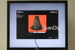

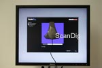
The profiling software exactly knows which color appears at the screen at the moment, e.g. a red tone (200,0,0). The colorimeter measures this colour and delivers the measurement value via an USB cable to the software, e.g. (190,0,0). Then the profiling software compares the measured red tone (190,0,0) with the desired red tone (200,0,0) and calculates one entry in the ICC profile.
The ICC profile for the monitor is created from numerous measurement values and their comparison whith the corresponding given value. This colour profile is stored centrally in the profile folder of the computer and can be used as standard profile for the connected monitor. Under Windows the profile choise is done in the dialogue display under extended in the file card colour management.
At the profiling of a screen singular colours are displayed and measured with a colorimeter and then are compared with the given values. From the differences of the singular measurements an individual correction profile is created.
Professional screen calibration tools allow the creation of individual monitor profiles, so that you can switch beween serveral profiles dependent on your application. It is very important at the creation of a profile that the used monitor has been on for more than half an hour so that it is already warm, and that the profile is created under those light circumstances, under which it will be used later. If you make professional image editing you should create different profiles, for instance one for daylight and one for evening work under artificial light.
At this point I want to clarify two widely spread mistakes: If you think that two identical monitors can use the same profile, you are completely wrong. Even two equal devices may have large aberrations from each other; otherwise a monitor manufacturer would deliver an appropriate profile with each monitor. Indeed there are ready-to-use screen profiles for singular screens from some manufacturers. However they never can be so precise as a self-created profile.
And the second mistake I want to clear is the belief that you can let your monitor calibrate by a service provider in order to avoid buying a colorimeter and appropriate software. In practice monitors (no matter if tube or TFTs) change the display quality in the course of the time so that they should be recalibrated in regular intervals (every 2-4 weeks).
Calibration and profiling of a scanner
At the monitor calibration in the previous chapter the colorimeter provided a back coupling to the PC via the USB cable und so reated a closed measurement loop. At the profiling process of a scanner we do not need an additional measurement device, since the scanner already has the back coupling to the PC.
Whilst at the monitor calibration the calibration software just displays reference colors at the screen, for the measurement of a scanner we need a reference model, in order to compare the scan results with the reference colours. At the scanner profiling process a reference target with a reference file closes the measurement loop. This measuring loop is shown in the adjacent figure 7.
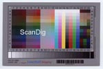
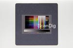
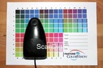
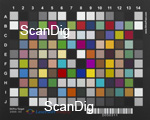
In order to measure a scanner we need a normed template with reference colours. Such a template is called target, and especially for scanners there are so-called IT-8 targets, with which the colour calibration (often as IT-8 calibration designated) can be done. IT-8 targets are available in different sizes, for instance in a mounted 35mm slide (see figure 8) for the calibration of film scanners or as a larger template (e.g. 10x15 cm) for the calibration of flat bed scanners (see figure 9).
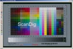
An IT-8 calibration target contains 264 colour fields and a 24 stepped grey skale (see figures). These singular colour fields have to be captured by the scanner. Figure 10 shows this procedure in the SilverFast software: A the IT-8 calibration process the user creates a big frame around the reference marks on the target; within this large frame the software automatically creates small frames within the singular colour fields.
This single colour fields are then scanned and as a result the scan software receives scan data with the actually measured colours. Depending on the scanner model the colours deviate more or less from the reference colour values. The profiling software needs a reference table for the comparison of the measured colours with the reference colour values. This reference table is delivered together with the IT-8 target. From the difference of the measured colours and the reference colours the calibration software creates an ICC profile for the scanner. Example: In the field L-15 there is a bright yellow with the color values (255,255,0). If the scanner digitizes this colour field with the result (250,240,0), the difference of the given value and the actual value goes as an entry into the ICC profile and thus can be used for the colour correction.
At the scanner profiling process a standardized IT-8 target is scanned. From the comparison of the measured colors with the reference colour table the profiling software calculates the ICC profile for the scanner.
The IT-8 calibration of a film scanner or a flat bed scanner is a very simple and quick matter: Insert the IT-8 target, start the calibration process, draw a limiting frame, start the calibration. The complete procedure is finished within a few minutes. For the IT-8 calibration of a scanner no extra measurement instrument is needed like for the calibration of a screen, only an IT-8 target and a software, which does the IT-8 calibration, are needed. The scan software SilverFast includes the IT-8 calibration function within the Ai-Studio version. The most manufacturer scan-programs cannot perform an IT-8 colour calibration, so that you need the professional scan software SilverFast Ai Studio.
If you have created an ICC profile for your scanner you can use it for the correction of all future scans. A good scan software like SilverFast makes that automatically by assigning the correction profile to each scan automatically. As a result one obtains a corrected scan file in the Adobe® RGB colour space. So you will never see the original uncorrected image. Insofar the IT-8 calibration at a scanner leads to an improvement of the image quality of all scans; the effort for it takes only a couple of minutes.
Similar to the monitor calibration also at the scanner profiling process it is possible/advisable to create several profile, since an IT-8 target is always made for a specific film type. For example, if you intend to digitize Kodak and Fuji films you should buy both a Kodak IT-8 Target and a Fuji IT-8 Target in order to create an own profile for each of the two film types.
What I have written about the screen calibration in the previous chapter also holds for the scanner calibration: Also for a scanner it is not sufficient to do the calibration once, but you should repeat it in regular time distances, for instance once per month. And of course you cannot transfer the profile from one scanner to another equal scanner, since the profiling is really individual for a specific device with its own errors and not for complete scanner series.
Profiling of a printer
Let us come to the calibration or the profiling, respectively, of a colour printer or a photo printer. If we compare the following figure 11 with the corresponding figure 5 for the the calibration of a computer screen, then we find a pretty similar procedure: The profiling software prints test colours on the printer, which then are measured by a special measurement instrument and sent back to the PC through an USB cable.
At the monitor calibration the calibration software displays one colour by one; the singular colours are then measured by a colorimeter. At the printer profiling a complete test chart with numerous colour fields is printed on the printer. A a result one obtains a printed test chart with many singular colour fields, see for example figure 12. Such a test chart has similarities with an IT-8 target, which is used for the scanner profiling. However, whilst an IT-8 test target has a fix nomber of colour fields, for the printer profilation there are different test charts. It is clear, that a profiling process is the more precise the more singular colour fields there are on the test chat. With the profiling softwareSpyder PRINT one can choose how many colour fields one whishes to use, for instance a simple target with 150 colour fields, a better target with 2256 fields or even en expert target with 729 colour fields.
Each single colour field has to be measured then, and it is clear, that more colour fields do not mean only a higher precision of the resulting profile but also a tremendous effort. FOr the measuring of the singular colour fields not a colorimeter can be used as for the monitor calibration, since such an instrument only can detect self illuminating objects. Instead a more complicated, expensive spectralphotometer must be used for the printer calibration. Such a measurement instrument has the shape of a computer mouse; its peak has to be put on each colour field and then the measurement has to be carried out with a butoon click.
Whiles a monitor calibration or a scanner profiling is done within a few minutes a printer calibration with 200 colour fields takes approximately one hour, and even longer the more colour fields are used. Like at the monitor calibration the measured colour fields are sent to the computer via a USB cable, so that the measurement loop is closed. The profiling software compares the measured values with the reference values for the test chart and calculates the printer profile from the difference. Since for printer profiles look-up tables are used the ICC profile for the printer is larger and more more pricise if more colour fields are measured.
At the printer calibration process a test chart is printed. The singular colour fields of the chart are measured with the help of a spectralphotometer. From the difference of the measured values with the reference values the profiling software creates the printer ICC profile.
I think I do not need to ention explicitly, that an ICC profile for one printer cannot transferred to an equal other printer; and like for monitors and scanners also for printers holds that every devices has its own colour fields which only can be corrected with an individual printer profile.
In the chapter about monitor calibration I have denoted that you should create different profiles for different light conditions; at the scanner calibration several profiles were needed for different film types. Is there any reason to create several printer profiles? Yes, even if a printer semms to be a pretty simple device, it has two variable aspects: the printer paper and the ink cartriges. If you ever have made a high-value print on two different sorts of paper or with two different inks, maybe from different manufacturers, you know the differences which such a change of the material might cause. In order to achieve an optimum print quality for photos you create an own printer profile for each paper-ink-combination and choose it before printing a picture.
A printer profile is chosen in the settings of the installed printer. The selected profile then is used at any following print, i.e. the colour values within the image to be printed are automatically corrected by the printer driver using the chosen ICC profile.
Profiling a digital camera
Many useres have calibrated their computer monitor since the result can be seen immediately after the calibration process. Many users calibrate their printer, too, so that it prints on paper, what on the calibrated screen can be seen. Ans also the calibration of a film scanner with an IT-8 target is a matter of course nowadays. However, that also a digital camera can bei calibrated, many hobby photographers cannot even imagine. And everything works pretty similar to a scanner calibration:
While the scanner scans an IT-8 target you have to take a picture of a ditital camera target (no IT-8 target) with your digital camera. Digital camera targets are available in different sizes, as a compact pocket target with 10x13cm and as a large studio target with a size of 17x21cm. Similar to an IT-8 calibration target also a digital camera target consists of sveral colour fields, 140 in total. These colour fields include reference colours, which colour values are stored in a reference table. When taking a picture of that target it is important that no reflexions occur and that the target is illuminated equally. On our website about the tool SilverFast DCPro we have shwon a studio equipment and have described how to perform an optimal camera profiling.
After taking a picture of the digital camera target the resulting image file (raw format) is loaded into the corresponding software. Within that software the measured colour valuels are compared with the reference values, which are stored in the reference file, which belongs to the target, and from the differences a kind of error table is created. From this the individual ICC profile for the digital camera is created. This ICC profile is stored with a significant name and then will be used for the automatic correction of digital photos.
At the profiling process for a digital camera first a specific digital camera target is photographed. Then the picture is loaded into a special software and the measured colour values are compared with the reference values. From this comparison the software creates the ICC correction profile.
This procedure with the automatic image correction only works if you make raw data with your digital camera and process them with the specific software. The images of the digital camera are still defective; however they will be corrected automatically within the processin software with the ICC profile. The result are better, true colour digital photos, which need less image editing work than normal images from a digital camera.
While a computer monitor is calibrated for different light situations, a printer is profiled for different paper-ink combinations and a scanner is profiled for different film types, for a digital camera different profiles for different light situations are made. For instance one creates one profile for the photo studio and one for outside in the nature.
Of course for digital cameras the same remark is valied like for scanners, screens and printers: It is not sufficient to make the digital camera profiling process only once. Also the sonsor and the optics of a digital camera vary and change their quality in the course of the time, so that a new calibration has to be done in regular time intervals.
Handling of correction profiles in a colour management process
In the previous subchapters we have seen how an ICC profile is created for a scanner, a monitor and a printer. Even if I have explicated the use of the singular profiles in the particular chapters, in the following I want to go into the handling of the profiles in a closed colour management process in summary.
Assume we have calibrated our scanner with an IT-8 calibration target like described above, we have measured our computer screen with the help of a colorimeter and created a monitor profile and we have measured our printer with a spectrophotometer and created a printer profile. Then nothing should stand in our way to see real colour scans on our monitor and get them printed by our printer.
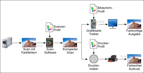
Figure 15 shows the complete work flow for scanning an image and displaying it on a computer monitor and printing it on a printer by using the colour profiles for the particular devices. Our film scanner first delivers faulty scan data, to which the ICC correction profile is added in the scan software. Together with the correction profile the scan data become free of colour errors. A software which is colour management compatible like Adobe® Photoshop® shows the corrected image on the basis of the included ICC profile. Since a good scan software like SilverFast automatically appends the correction profile to the image filme and a good image editing software like Photoshop® uses that correction profile automatically for the colour correction, the user does not notice something from this colour correction at all.
At the output of an image file at the computer monitor the colours would be falsified if the screen is neither calibrated nor profild. Our display driver gets the corrected scan file, however, the uncalibrated screen would not display it in true colours. Because of this reason the graphics driver corrects the colours in cooperation with a colour management capable image viewer (e.g. Photoshop®) so that they are displayed at the screen correctly. To say it correctly, the erroneous scan files are corrected with the help of the input profile (scanner) and the output profile (monitor), so that they are finally displayed with true colours.
The same principle works at the output of our scan file on a printer: An unprofiled printer would print the correct scan file with colour errors. In order to compensate them the printer driver sends modified pixels to the printer by applicating the ICC printer profile. In this way it somehow falsifies the scan files in the contrary direction of the printer errors. Of course in practice it is not so trivial, however the principle works like described.
From the total image above it becomes clear that you always get true colour images if you profile all intput and output devices. It also becomes clear, that you do not need to profile your printer, if you watch your digital image only at the computer screen or order prints in a professional photo laboratory (which have calibrated printing machines). And of course you could do without a monitor calibration if you don't watch your images at a computer screen but print them only at a photo printer. If you do without a calibration of your scanner and have a calibrated monitor therefore, you can compensate the scanner deficit by correcting each image in an image editing program until the colours are true. In this way you can save about 100 € for a monitor calibration tool by spending hundreds of hours with image editing.
Colour management module, work and device colour space
If you have worked through the chapters above until this point you hopefully have learned and understood a lot. The learning target seems to be achieved and easily to implement: You calibrate all your input and output devices, for example by using the SilverFast scan software with IT-8 calibration for the scanner calibration, and by measuring the screen and the printer with an appropriate tool set, for instance the Datacolor SPYDER Studio. Thus you eliminate the colour errors of your devices and may expect true colour images in your digital image work flow.
If you calibrate your scanner, your digital camera, your monitor and your printer you have a complete colour management process and are rewarded with true colour pictures at the monitor or at the printer. Furthermore you save a lot of working time, since you can do without time-consuming image corrections.
99,999% of all users can stop reading at this point, if they obey all the tips from above and calibrate all devices. For professional users I want to mention a topic in the following which also has to be considered in the colour management process.
We have learned that we always have color-fast images, if we profile all input and output devices. So a colourfast print of a digitized slide or a digital camera picture should succeed. Principally right, but: Is our output device technically available to render all colours which are contained in an image file? Or differently asked: Can a piece of high-value photographic paper show the same colors which our eye can see in nature or which are contained on a photographic film? Can a sufficiently large computer monitor display colours so clearly that you cannot differ any more if it is a computer image or the reality? The answer is a clear NO.
The reason for the clear NO is that any electrical device only can display a limited nomber of colours. All displayable colours of an input or output device are called device colour space or colour gamut. Colours which are outside of the device gamut cannot be captured or rendered by the device.
Each device (scanner, digital camera, monitor, printer) can show colors only within its device specific colour gamut.
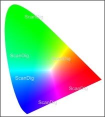
On our page Colour reception you can read that our eye can percept an infinite nomber of colours. And anyway there are still numerous colour tones, which the human eye cannot capture, for instance in the infra red area. Some animal is superior to us in this point. In the above subchapter about the Reference colour space Lab we have learned that in the shoe sole diagram of the ICE all colours, which are perceptable by the human eye are contained. Figure 16 shows this reference gamut again.
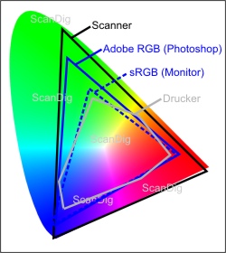
In figure 16 there are additional gamuts in the drawing. You recognize that a scanner has a pretter large colour space, but still only captures about 2/3 of all Lab colours. You recognize additionally, that a scanner also can capture colour tones (e.g. in the infrared area) which the human eye cannot see any more (scanner gammut limit exterior of the Lab diagram).
The gamut with the color blue named Adobe® RGB is a pure working gamut, with which you typically work within Adobe® Photoshop®. The colour space sRGB also is a pure work gamut, which is used by digital cameras and monitors. It is significantly smaller than the Adobe® RGB gamut. Finally there is the gamut of a printer sketched (grey line). And you recognize clearly, that this gamut contains much less colours than a monitor or a scanner. Indeed, the printer has the smallest gamut of all devices in a digital process chain.
The figure illustrates what we already know from the practical work: In the nature (compete diagram) there are much more colours than we can capture with any digital camera or with any photographic film + scanner. A monitor can display significantly less colours than a slide projector, for example. And even more smaller the colour range beomes if we print images on printers or printing presses. (Remark:Who remembers the time, when an ink jet printer could not print real black, beacause black was created by the three print colours CMY?)
The size of the gamut reduces step by step in the chain nature - human eye -photographic film - scanner - Photoshop® (Adobe® RGB) - screen(sRGB), digital camera (sRGB) - printer.
The comparison of gamuts of scanner, monitor and printer in figure 16 makes clear that it is no matter of course even if all devices are calibrated that an image on a colour printer appears equally to the same image on a monitor. If colours, which a scanner captures but a printer cannot print, are just cut off, one obtains catastrophic, pretty useless prints. Thus there must be any mechanism how to deal with different colour spaces. And so we come to a central component in an operating system, the Colour Management Module (CMM).
The Color Management Module (CMM) is a central service module, which performs the conversion of gamuts by colour profiles. Figure 17 shows that there are different CMM modues. On Apple computers there is a CMM system with the nam ColorSync, on Windows PCs it is the ICM (Image Color Matching). Since Windows Vista there is a new CMM, the Windows Color System (WCS), however, it never has really established. Adobe® Photoshop® even offers an own Color Matching System an, namely the Adobe® Color Engine (ACE).
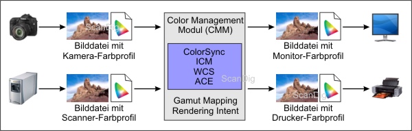
What does a Color Management System do? In short, it does the conversion of gamuts (gamut-mapping) and offers this as a service for different software products, for instance image editing programs our drivers. The procedure, how the conversion is to be done, is called Rendering Intent. In professional image editing programs like Adobe® Photoshop® the rendering intent can be chosen from a list. A simple procedure for the conversion of an sRGB image into CMYK print colors would be the cutting off of colours, like mentioned abouve (with catastrophic results for the image quality). A mmore complicated rendering intent would be the projecting of colors, which lie outside of the target gamut on toe exterior limit of the target gamut. Another procedure would be the compression of all colours into the target gamut. The detailed treatment of rendering intents would exceed this chapter. For this topic there is detailed literature available.
The Colour Management Module (CMM) makes the conversion of colour gamuts with color profiles. The conversion rules are designated as Rendering Intents.
What should you remember as a professional or semi-professional user? Looking at the figure 16 you should keep in mind that the colour gamuts become smaller and smaller in the chain nature - eye - film - scanner - Photoshop® - monitor - scanner. In Photoshop® one usually works in the Adobe® RGB colour gamut, which can handle much more colours than a screen or a printer can display or print. If you only work for the internet you can restrict yourself to the smaller sRGB gamut. Very good scanners can create image files in the raw format or in the larger Adobe® RGB colour gamut. You should use that feature, if available within the scan software, since the you still can reduce the nomber of colors later. Digital cameras usually create image files in the sRGB colour gamut.
You always should append the appropriate profile to an image file so that the CMM or Photoshop® know how to treat the colour values within the image file. Scan software programs, digital cameras and image editing programs usually offer a switch within the settings, which determines if the profile shall be appended to the image file or not.
At scanning or digitally photographing you should append the appropriate ICC profile to each single image, so that image editing programs know in which colour gamut the in the image file stored colour values have to be interpreted.
By the way, the simple user does not notice the existance of the Color Management Modul at all. It is a system which works silently in the background and does self-evident jobs like the conversion of monitor RGB colours into printer CMYK colours. However, if you open a foreign image or a scan without embedded profile in Photoshop® and gets a weird question, in which colour gamut the image editing work should be done or which profile should be assigned to the image, then you know now, after reading this chapter, that it is about the colour conversion with rendering intents.
Back to the index colour management
|
)
)
)
)
)
)
)
)